North Logiealmond Wind Farm
Design and Access Statement
4. Design Principles
This section of the DAS sets out the key design principles that were largely followed to inform the iterative design process. The Proposed Development followed an iterative design process using a core set of design principles, taking account of technical and environmental constraints, statutory engagement and responses from public consultation. This section sets out the iterative process and the design principles relevant to the Proposed Development. Section 5 sets out the details of design iterations and how consideration has been given to consultation and engagement.
4.1 The Iterative Design Process
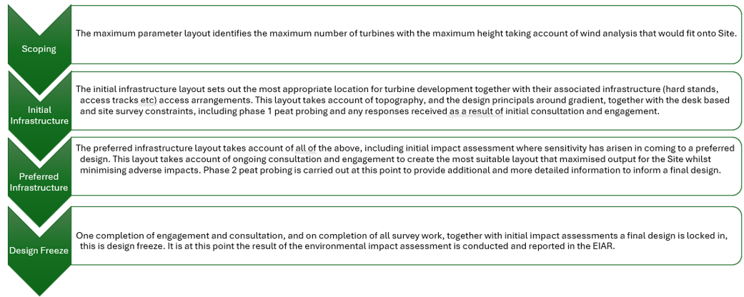
The Proposed Development was subject to a systematic iterative design process. This comprised the identification of:
Maximum parameter layout (a scoping layout)
Initial Infrastructure Layout (Design Chill 1)
Preferred Infrastructure Layout (Design Chill 2)
Design Freeze
4.2 The Design Strategy
The design strategy for the key elements of the Proposed Development has considered the following objectives:
Maximise the energy yield by optimising turbine locations and reducing wake effects that diminish efficiency;
Develop a well composed layout minimising horizontal spread in views at settlements, residential properties, heritage assets and the Highland Boundary Fault;
To protect the amenity of residents of nearby properties by addressing shadow flicker, visual amenity and operational noise;
To limit impacts on peat;
To minimise the overall footprint of the infrastructure;
To minimise the number of water crossings;
To create opportunities within the Site to restore and enhance habitats and biodiversity;
To reduce ornithological risks by incorporating bird related considerations, including reducing collision risk;
To ensure that the Proposed Development is constructible and seeks to design out construction risks at an early stage; and
To ensure the layout considers and respects other environmental and technical constraints throughout the design process.
4.3 The Design Principles
The core design principles for the Proposed Development included a layout that maximised the output of renewable energy whilst limiting the potential for environmental impacts during construction and operation. Factors influencing the suitability of the layout included:
A good wind resource;
Suitable wind speeds and quality of wind flow to optimise generation outputs;
Suitable separation distance from dwellings so that unacceptable impacts related to potential noise, shadow flicker and residential visual amenity can be avoided;
Willing landowners;
Not located in any national or local landscape designations;
Not within a cultural heritage designation including Conservation Area, Historic Garden & Designated Landscape, world heritage site, a Scheduled Ancient Monument or directly impacting a listed building;
Not within ecological designations of international or national importance;
Suitable public road network for the transportation of all wind farm components, including Abnormal Indivisible Loads (AIL) deliveries of elements such as blades;
Close proximity to a grid connection;
Topography of the Site is compatible with the construction and operation of a commercial-scale wind farm;
Compliance with the Scottish Government aspirations for demonstrably better energy yields;
A substantive contribution to the UK and Scottish Government’s renewable energy targets; and
Considerate of policy contained within NPF4 and the local Development Plan 2.
Construction of floating tracks on a cross gradient of >5% is not permitted unless additional geotechnical assessment is carried out.
Access roads passing through areas of wind turbine generator hardstanding shall be considered as hardstanding.
Axle loading and crane outrigger loadings have not been considered at this stage. However, the applied geometry has been used for preparation of the InfraWorks model to allow estimated construction areas to be prepared. A track thickness of 600mm is assumed.
Floating hardstandings will not be permitted.
Temporary construction compound areas for the shared use of construction contractors have a been assumed to be 100 m x 50 m.
Minimum access tracks widths:
Straight road to be 5 m effective running width.
Bends to be 6 m effective running width.
Passing places to be provided (at least) every 500m. Access track intersections can also be used as a lay-by function if they comply with the required dimensions.
Turning heads must be no more than 200m from wind turbine generator hardstanding. No reversing operations of loaded trailers.
4.4 Technical Design Considerations
Wind Turbine Scale
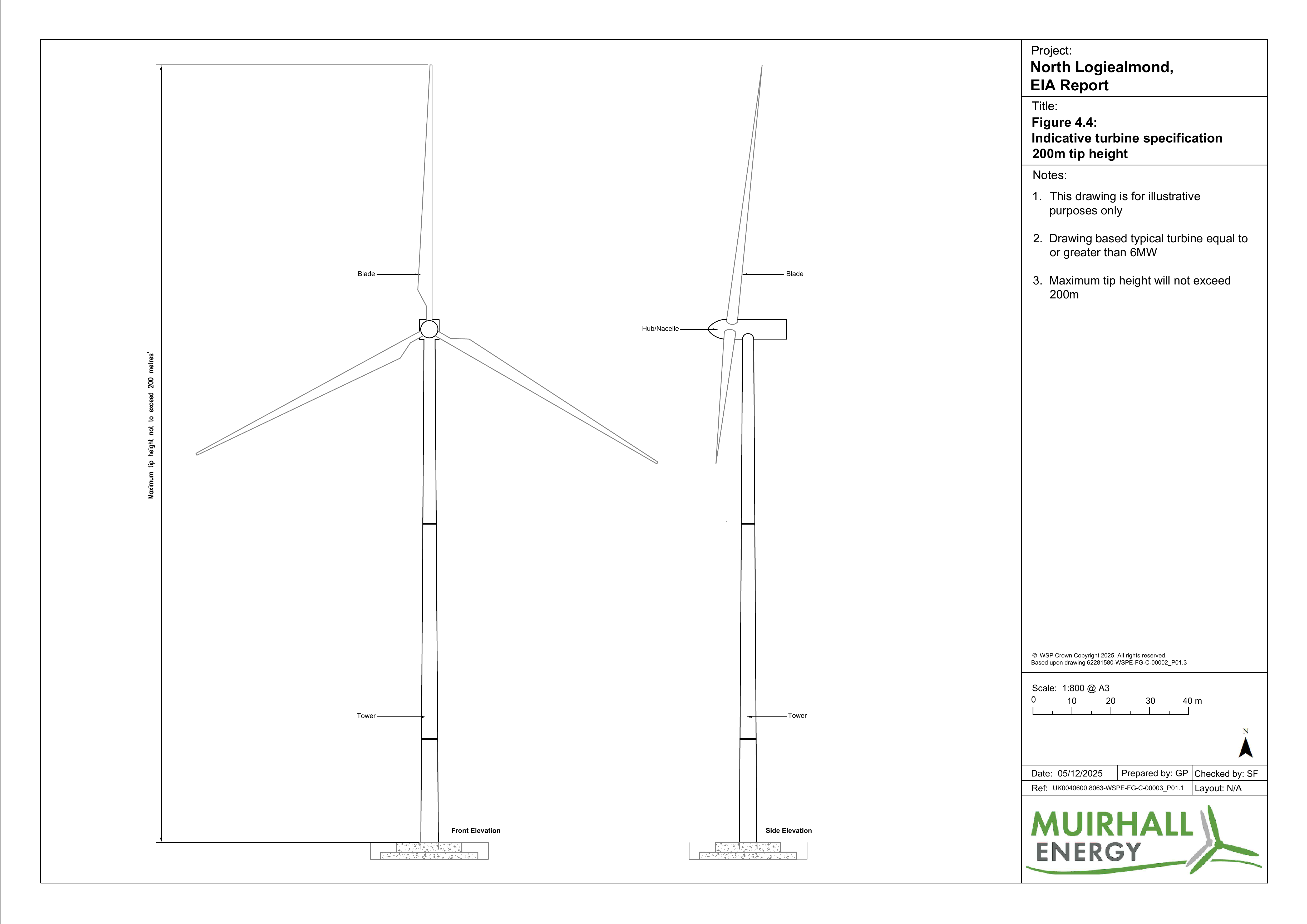
Larger turbines, with larger rotor diameters (longer blades), allow more air mass to pass through the rotor per second. This increases the energy available to generate electricity. Turbine dimensions were considered to maximise the rotor diameter. The final selection of the turbine tip heights of up to 180 m and 200 m was considered to represent the best balance in terms of energy yield, landscape fit and the scale of the turbine that is currently capable of being transported to the Site.
A further design consideration on turbine scale relates to the availability of the turbine to the market at the time of construction. The onshore wind industry is experiencing a significant reduction in the supply of smaller wind turbines, and therefore, it is unlikely that a range of smaller turbines (e.g. 150 m) would be available at competitive prices by the time the Proposed Development would be constructed. However, the Applicant has looked at 150 m tip height turbines across the Site and found that it would not be commercially viable for the Proposed Development.
Wind Analysis
Wind resource analysis and wake modelling have been undertaken to identify the areas of the Site with the greatest potential for energy generation.
To operate efficiently, turbines must be suitably spaced relative to the prevailing wind direction. Turbines positioned too closely can create wake effects, reducing efficiency and increasing the need for operational maintenance and down time. Conversely, excessive spacing reduces the potential for maximising capacity at a site. As a result, and in line with good design practice, the following ellipses were applied to the Proposed Development:
Spacing of approximately five times rotor diameters in the prevailing wind direction; and
Approximately three rotor diameters cross wind (5 RD X 3 RD)
This design principle provides a balance between maximising energy yield and maintaining operational efficiency.
Topography and Gradient
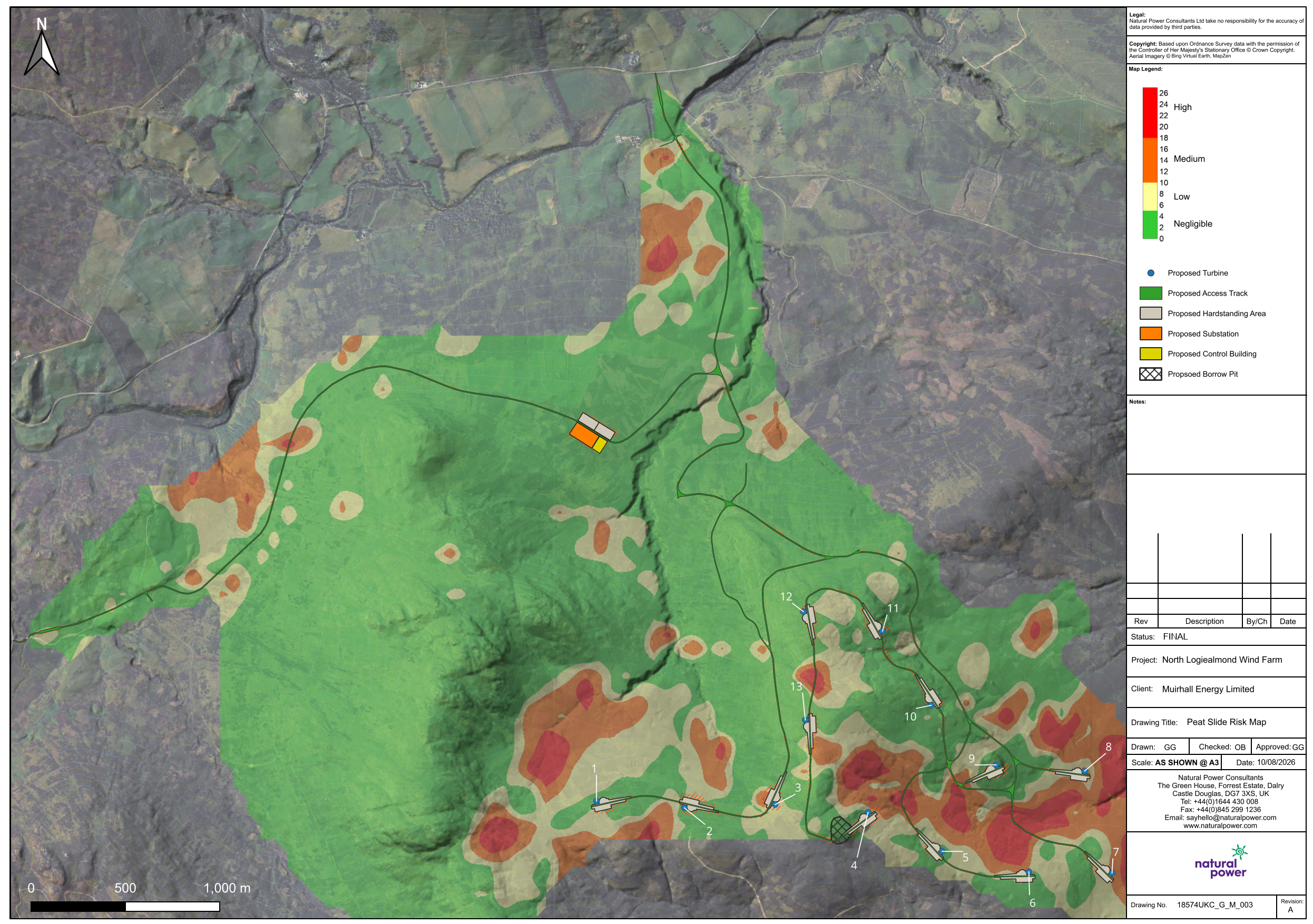
The Proposed Development covers an area of approximately 803.4 ha, and the maximum Above Ordnance Datum (AOD) of the site is ~600 m. Figure A7.5.4: Risk Map (Figure 1) sets out the peat slide risk potential.
The design philosophy behind the layout has taken into account a number of factors including topography, ground conditions and construction parameters, and has been based on best practice methodology developed at other wind farm sites.
An embedded mitigation measure includes the avoidance of steep gradients within the design, which helps to reduce potential effects on sensitive receptors such as watercourses and associated Water Framework Directive (WFD) surface water bodies, soils and peat, areas at risk of downstream flooding, and surface water resources.
Turbine foundations and hardstand areas located up-gradient from sensitive habitats could disrupt shallow groundwater flow from dewatering and diversion of flow paths.
Turbine foundations and hardstand areas located down-gradient from sensitive habitats could cause a temporary lowering of the water table from dewatering.
Access tracks, drainage ditches and cable trenches located up-gradient from sensitive habitats could disrupt and divert shallow groundwater flow-paths.
Deep excavations, such as those required for the turbine foundations, have the potential to disrupt the shallow groundwater system and bedrock geology. Surface water ingress is minimised by utilising upgradient cut-off drains or other drainage measures. The installation of cut-off drains has the potential to lower local groundwater levels within surrounding soils.
Landscape and visual amenity
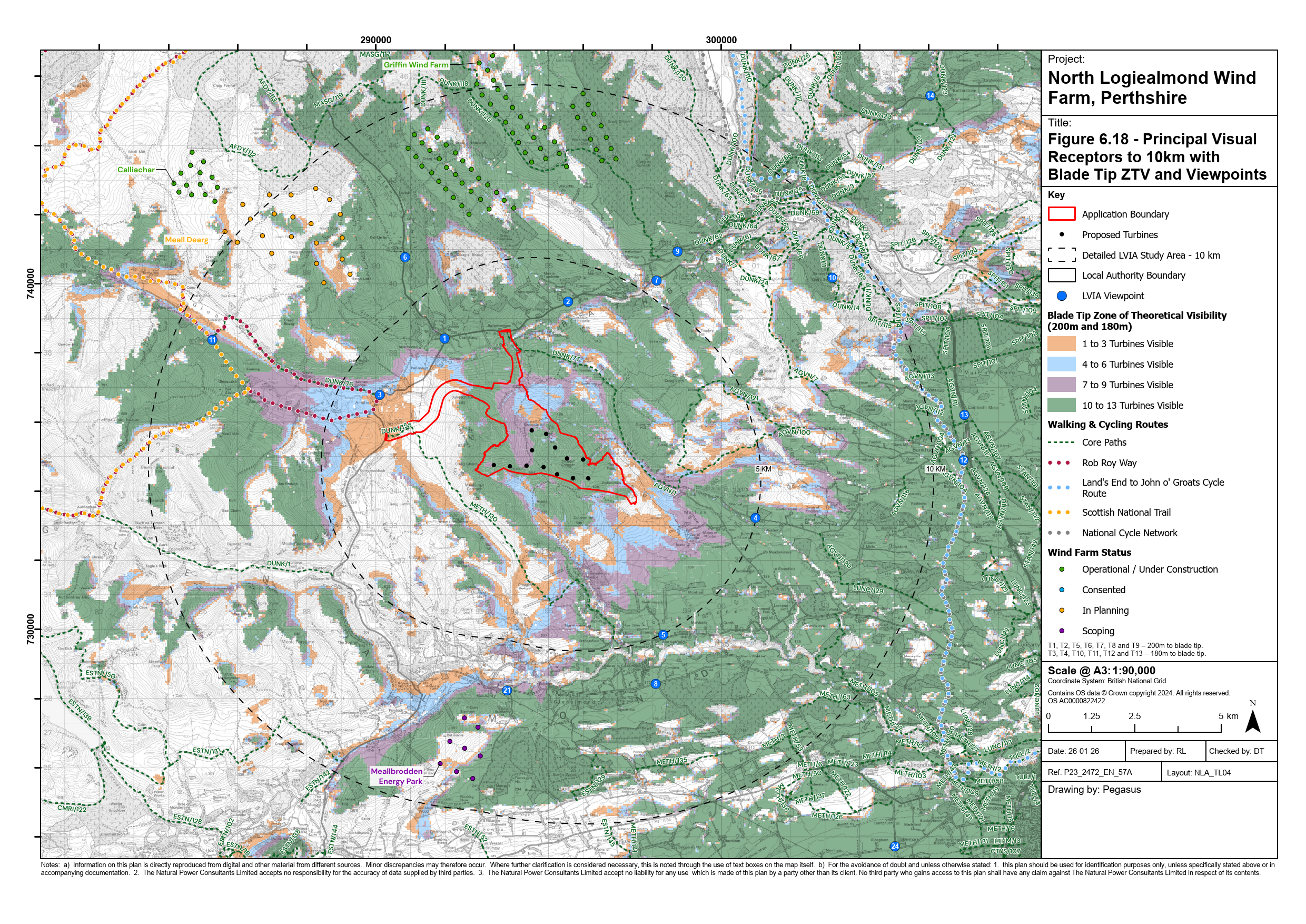
The wind turbine layout design is a key factor influencing how the Proposed Development relates to the surrounding landscape and how it is perceived in views. Its appearance, both as an individual development within the landscape and in combination with other wind energy developments in the wider area, was therefore a key consideration during the design process. EIA Figure 6.18 (Figure 2) sets out the principal visual receptors.
Landscape and visual input to the design is informed by NatureScot’s Siting and Designing Wind Farms in the Landscape (Version 3a, 2017), professional experience and fieldwork observations.
In addition to the Design Principles, the following design considerations were taken into account during the iterative design process:
Reducing the prominence of the Proposed Development in views from the River Tay (Dunkeld) National Scenic Area;
Limiting the horizontal spread of the Proposed Development in key views, including those associated with the Highland Boundary Fault;
Positioning turbines of differing heights to ensure that the development appears as a coherent group within the landscape and to avoid isolated or outlying turbines;
Setting the Proposed Development back where possible and utilising landform to prevent it from appearing as an overbearing feature in the landscape;
Responding to nearby wind energy developments, including the operational Griffin and Calliachar Wind Farms and proposed developments such as Meall Dearg and Meallbrodden, to achieve a balanced relationship within the wider landscape; and
Avoiding the most valued landscape features within the Site where practicable and seeking opportunities for enhancement where possible.
Biodiversity
Ecological surveys have been carried out across the Site since 2023. These surveys, together with the desk based constraints, are mapped and taken into account throughout the iterative design process. EIA Figure 8.2-8.5 (Figure 3) sets out the National Vegetation Classification (NVC) for the Site.
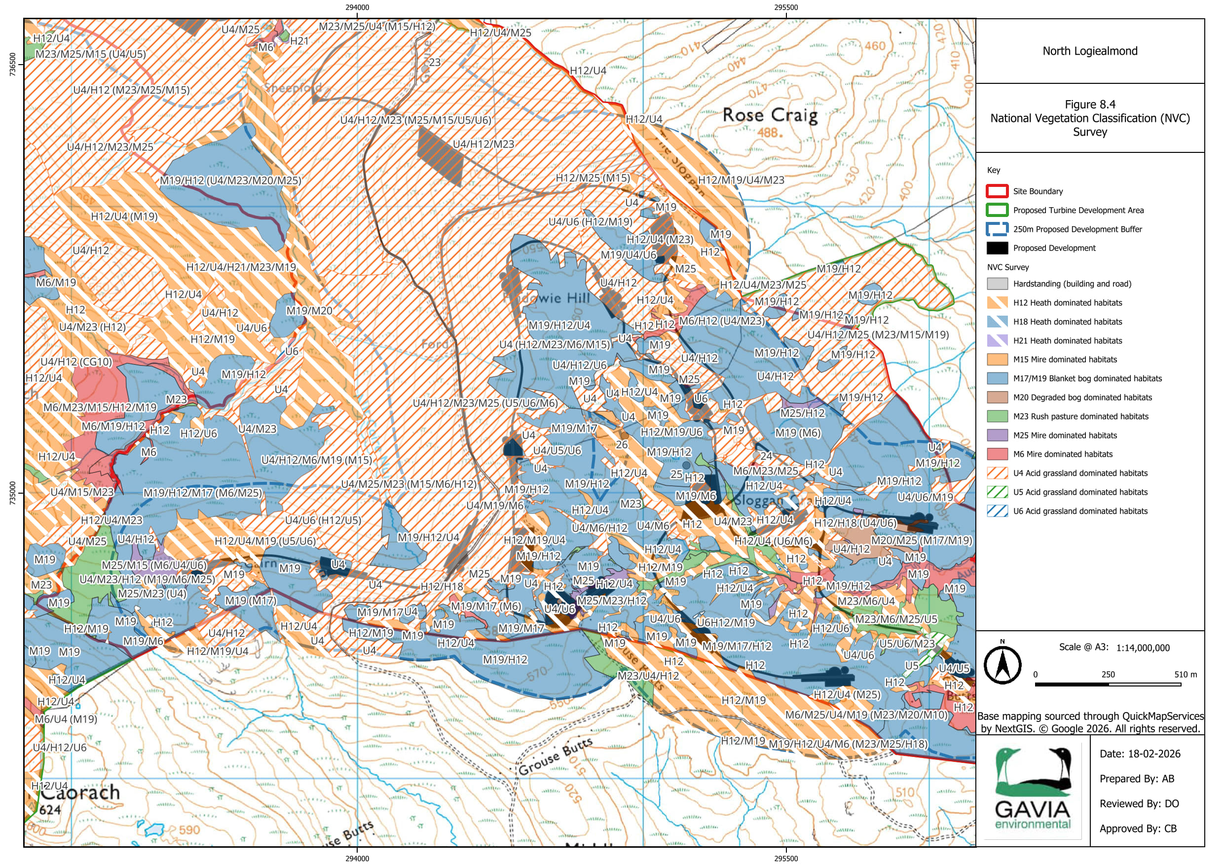
The design has sought to avoid sensitive habitats and species where practicable, incorporating appropriate buffers and mitigation measures.
The ecology surveys that have taken place include:
UK habitats survey;
NVC survey ; and
Protected species surveys (including bats, pine marten (see photo), badger, otter, water vole, red squirrel and fish).
Ornithology surveys have also been undertaken across the Site over a 24-month period between 2023 and 2025, including:

Flight activity/Vantage Point (VP) surveys;
Breeding raptor surveys;
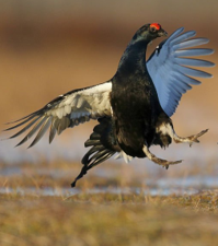
Black grouse surveys (see Image); and
Moorland breeding bird surveys.
Noise
For the purposes of early constraints mapping, a standoff distance of 1 km was applied to residential properties in the vicinity of the turbine area.
No residential properties are located within 1 km of any proposed turbine.
The water environment, peat and peat slide risk
The core design considerations for the water environment include:
50 m stand off from water courses;
250 m stand off from sensitive water receptors (private water supplies (PWS), groundwater dependant terrestrial ecosystems (GWDTEs);
Minimising water course crossings);
Maximising the use of existing tracks and water course crossings;
Avoiding areas of deepest peat (peat depths of 1 m or more);
Use of floating tracks on areas of peat in excess of 1m (where gradient allows); and
Minimising the potential for peat slide risk.
EIA Figure 7.3 (Figure 4) sets out the interpolated peat depth map for the site.
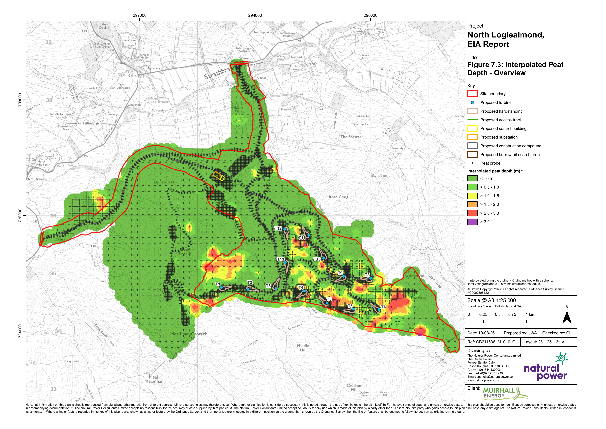
The Proposed Development incorporates embedded design principles to ensure safe and environmentally responsible construction on peatland. These include avoiding unnecessary excavation, preventing the concentration of loads on sensitive peat areas, and ensuring that drainage and surface water management do not adversely affect peat stability. Peat that requires temporary storage will be managed carefully to maintain its condition and will be reused on the Site where appropriate.
In accordance with SEPA guidance, a 50 m stand off has been applied around watercourses. The purpose of this stand off is to reduce the risk of runoff, loose sediment and potential pollutants entering watercourses, and allows space between development and watercourses to apply additional mitigation measures during construction to ensure pollutants don’t enter the watercourse.
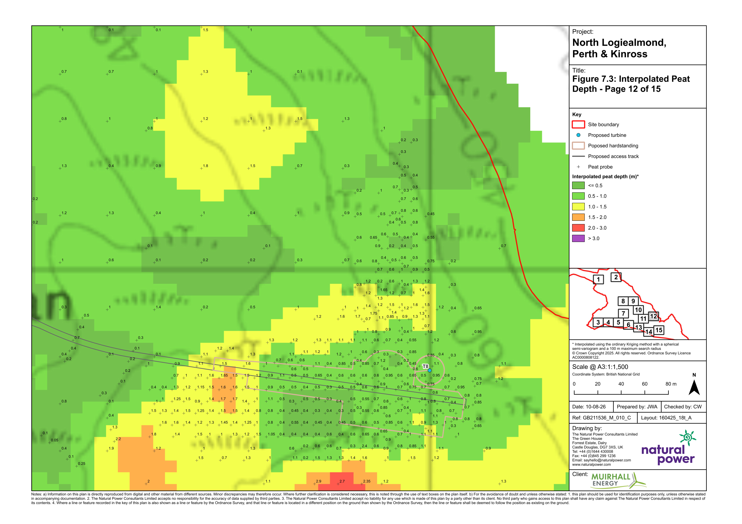
Phase 1 and phase 2 peat probing have been carried out, and all areas of the deepest peat and potential peat slide risk areas have been avoided. T8 is located close to areas of deeper peat (in excess of 1 m) with a small area of the hard stand in peat over 1m in depth (see extract from EIA Figure 7.3 (Figure 5)).
In some cases, the use of existing tracks, already within 50 m of drainage ditches, has been identified as the best option for design, as repurposing existing tracks will minimise the need for new tracks. In selected locations, a balance of constraints has necessitated the use of a narrower standoff.
Watercourse crossings have been minimised, and existing crossings would be used to reduce disturbance. There would be a total of 13 water course crossings within the Site.
PWSs within 2 km of the Site were reviewed, and only three were identified for further assessment. A GWDTEs assessment was undertaken in accordance with SEPA guidance to understand the presence and sensitivity of habitats within the Site.
While a number of habitats with potential groundwater dependence were recorded during the NVC survey, further consideration of local geology, hydrology and topography confirmed that only one habitat within the Study Area exhibits actual groundwater dependency, associated with a localised spring.
Consideration of peat depth and peat stability has been integral to the design of the Proposed Development. Surveys undertaken across the Site identified areas of deeper peat and localised peat slopes, and the layout has been developed to minimise disturbance to these features wherever practicable.
In locations where peat deposits are shallow, tracks are expected to be constructed on firm underlying material. However, where deeper peat is present, where reasonably practicable, the Applicant will consider floating track solutions that avoid unnecessary excavation and maintain the peat in situ, consistent with recognised best practice for peatland environments.
For measures relating to the peat slide risk, details have been provided in EIA Technical Appendix 7.5 Peat Landslide Risk Assessment. However, the following measures will be implemented for excavation and storage to address peat slide risk:
Avoid peat arisings being placed as local concentrated loads on peat slopes without first establishing the stability condition of the ground and slope system.
Stockpiling on areas of deep peat and in close proximity to steep slopes should be avoided.
Avoidance of uncontrolled and concentrated surface water discharge onto peat slopes as this may act as contributory factor to failure.
All water discharged from excavations during the construction phase should be directed away from all areas identified as susceptible to peat failure and should be managed by a suitably designed site drainage management plan.
All excavations where required should be adequately supported to prevent collapse and the destabilising peat deposits adjacent to excavations.
Cultural Heritage
The design of the Proposed Development has considered:
Designated heritage assets within the Site.
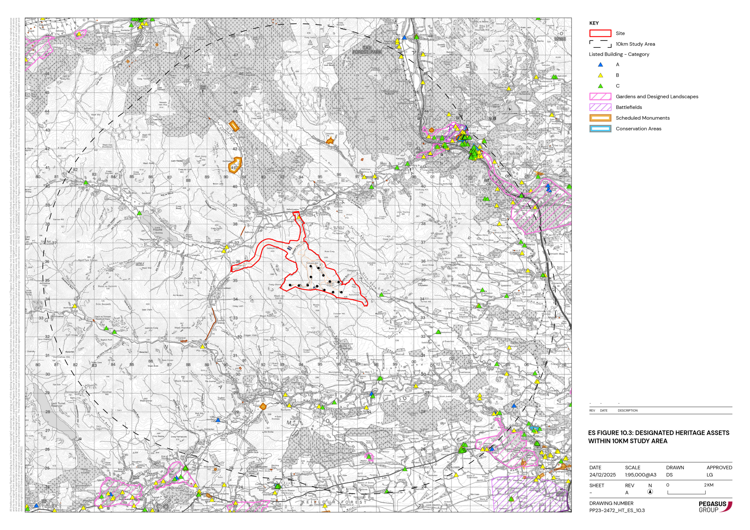
Designated heritage assets within 10 km of the Site Boundary.
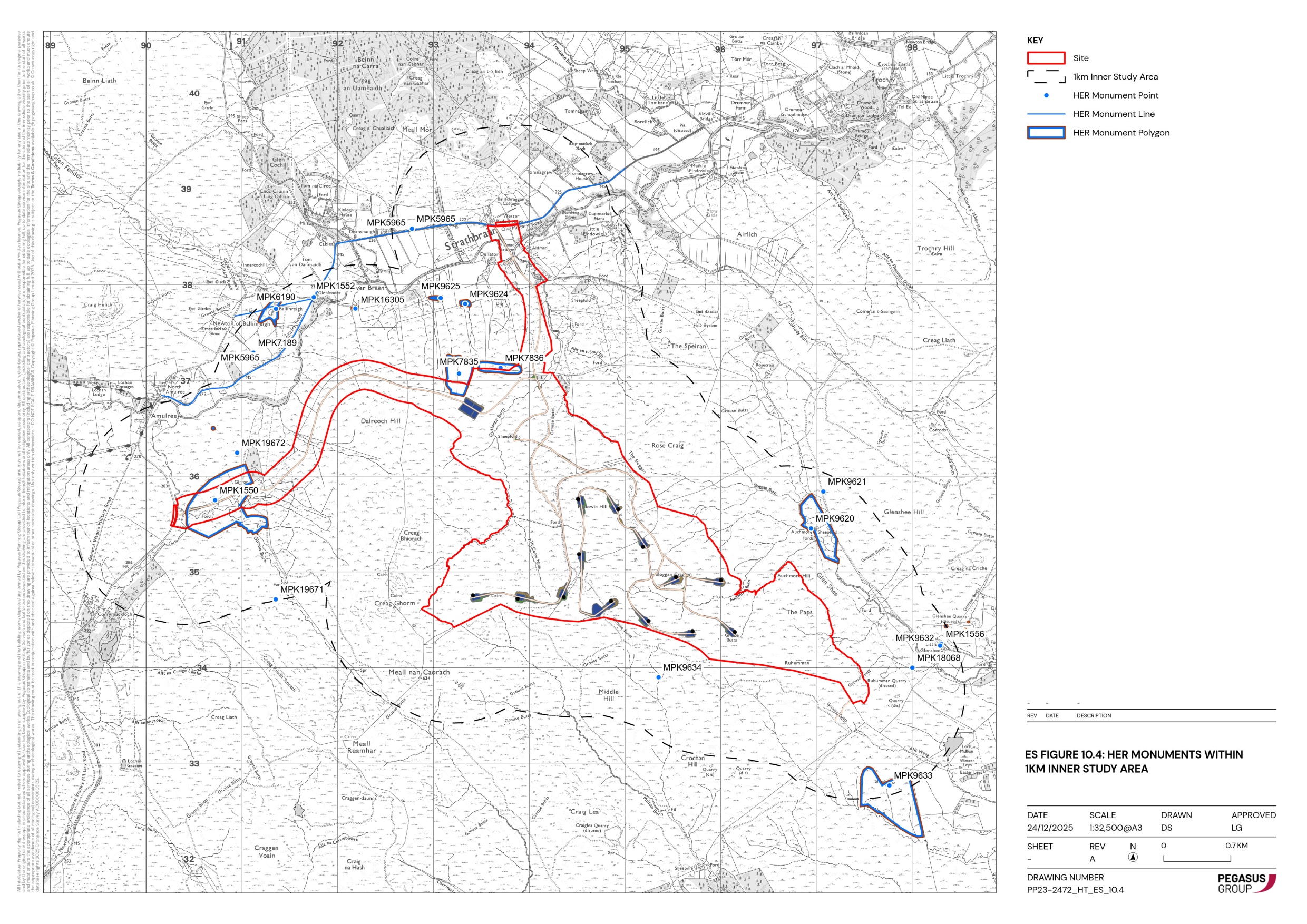
Non-designated historic assets (archaeological sites, findspots, locally significant buildings, locally historic landscapes) within 1 km of the Site Boundary.
Specific design considerations for archaeology and cultural heritage prioritise the avoidance of direct effects on any designated assets. The spread of the Proposed Development was compressed across the Site to create a more uniform appearance. T11 was moved, during Design Chill 2, slightly south further away from the Scheduled Monument Miekle Findowie. In terms of indirect effects, and similar to the landscape and visual amenity design considerations, the use of scale, location, topography and careful design to minimise adverse effects on designated assets.
Figure 10.3 (above) sets out the designated heritage assets within 10km, and an extract of those on the site is set out here.
There is one listed building located within the site boundary, as illustrated in Figure 10.4 (left).