North Logiealmond Wind Farm
Design and Access Statement
5. Design Evolution
5.1 The Needs case
Schedule 4, paragraph 2 of the Electricity Works (Environmental Impact Assessment) (Scotland) Regulations 2017 (the EIA Regulations), requires the consideration of reasonable alternatives in terms of development design, technology, location and the size and scale of the Proposed Development. Regulation 5(2)(d) of the EIA Regulations requires that an EIA report should include: “a description of the reasonable alternatives studied by the developer, which are relevant to the development and its specific characteristics, and an indication of the main reasons for the option chosen, taking into account the effects of the development on the environment”.
Notwithstanding this, the NPF4 has designated 18 National Developments in Scotland, one of which is out that the ‘on and off shore electricity generation, including electricity storage, from renewables exceeding 50 megawatts capacity’ (National Development 3). This means that the principle of need is already established. The designation of a project as a National Development in National Planning Framework 4 (NPF4) serves as the legal and policy acceptance that the project is required nationally.
5.2 Consideration of Alternatives
In considering alternatives, the Applicant has considered:
Different turbine and infrastructure layouts/locations within the Site;
Different turbine heights/dimensions;
Different Abnormal Indivisible Loads (AIL) routes to the Site;
Battery Energy Storage Systems (BESS); and
Solar.
BESS was initially considered to be co-located as part of the Proposed Development in the west of the Site. This was not progressed due to uncertainties over the outcome of national grid reform and emerging grid policy.
Solar was also initially considered as part of the Proposed Development and discounted due to the orientation and topography of the Site.
5.3 Design Iterations
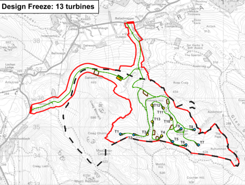
The Proposed Development has gone through four principal iterations of the layout (the layout presented at scoping and three subsequent iterations), which have been developed at different stages in the project design process. The four layouts are illustrated below. These show how the design has evolved through each of the design stages of the EIA process.
The Proposed Development layout has evolved through a structured, iterative design process informed by environmental constraints, technical considerations and consultation feedback. Four key design stages were identified, as set out below.
1. Scoping: 20 Turbines
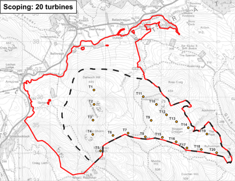
A design workshop was held on 30 July 2024 to review the initial scoping turbine layout with environmental technical specialists.
The design was informed by a range of baseline surveys and assessments, including:
Ornithological and protected species surveys;
Phase 1 peat depth probing;
Ecological surveys;
Telecommunications impact assessment;
Site topography survey; and
Initial visibility analysis.
Turbine positions were refined in response to identified constraints, including areas of deep peat, steep slopes, sensitive wildlife habitats and species, and initial landscape and visual considerations.
T1 was recommended to be moved slightly south on landscape and visual grounds; and T6, T8, T12, T14, T16 and T20 were identified as being located in areas of deep peat, as informed by the Phase 1 depth surveys. Movement of these turbines was recommended.
This process informed the 20-turbine scoping layout, which formed the basis of the on which the Scoping Report submitted in October 2024, see EIA Technical Appendix 1.1.
2. Initial Infrastructure Layout (Design Chill 1): 18 Turbines
Following receipt of the Scoping Opinion and two community engagement events held in November 2024, a further design workshop was held in February 2025. This workshop reviewed the scoping layout in the context of consultee responses, community feedback, updated survey data and anticipated constraints, including the need for additional peat investigation.
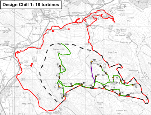
An initial refined infrastructure layout was also presented, enabling specialists to identify key areas of concern and provide targeted advice.
This informed a series of design changes, including the removal of two turbines from the scoping layout.
Key factors considered included:
Landscape and visual considerations, particularly feedback from communities on impacts to Amulree to the north west and Little Glenshee to the south east;
Potential ornithological constraints, including collision risk and barrier effects;
Proximity to sensitive bird species;
Peat depth and associated ground conditions; and
Local topography, particularly steeper slopes.
The proposed positions of T3, T6, T7-T10, T13 – T17 and T19 were identified for further peat probing, ahead of the Phase 2 Peat survey being conducted and recommended to avoid the deepest peat.
These refinements resulted in an 18‑turbine layout at a tip height of 200 m.
3. Preferred Infrastructure Layout (Design Chill 2): 17 Turbines
Consultation with HES, NatureScot, SEPA and PKC took place in May 2025, along with a second round of community engagement events, which informed the iterative design process.
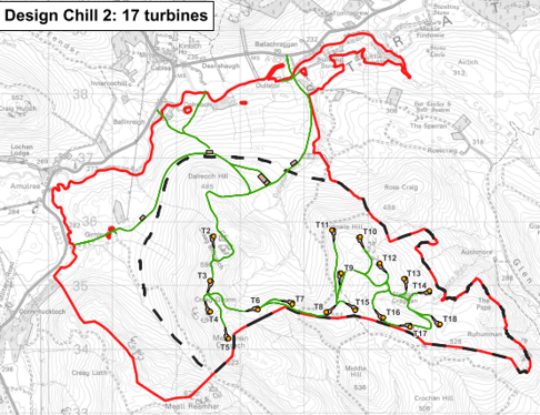
A further design workshop was held in June 2025 to review turbine positions and infrastructure in light of updated environmental data, consultee engagement, public consultation feedback and discussions with local community councils.
This workshop incorporated new survey information both in response to biodiversity and in response to additional peat probing.
Following additional peat probing and infrastructure design, further amendments were made to the 18-turbine layout. T6-T9 and T14-T18 were identified as being within areas of peat deeper than 1.5 m and recommended for relocation to avoid these areas. Turbines were subject to movement to mitigate impacts on deep peat.
T9 was noted to be particularly prominent in views from the south and southeast, and was a slight outlier from the NSA. As a result, T9 was removed, making the scheme a 17-turbine layout
Further refinements reduced the overall horizontal spread of the turbine array across the Site.
T11 was moved south slightly, further away from the Scheduled Monument Meikle Findowie. T18 was moved northwest, away from the southeastern Site Boundary, with consideration to views from Little Glenshee and further feedback from communities.
Further refinement reduced impacts on collision risk based on initial collision risk modelling.
This stage also introduced potential access options, the northern and western access routes identified as preferred options, subject to further surveys and engagement prior to design freeze.
Borrow Pit search areas were identified at this stage.
These refinements resulted in a 17‑turbine layout at a tip height of 200 m.
4. Design Freeze layout:13 Turbines
Consultation with NatureScot on the updated Design Chill 2 layout in July 2025 identified continued concerns relating to potential effects on the River Tay NSA and the landscape characteristics of the Highland Boundary Fault.
In response to this feedback and following further assessment and design refinement, four turbines located on the western ridge of the Site were removed. This decision was also informed by continued feedback from the community on properties at Amulree and the Glen Quaich Local Landscape Area to the west of the Site.
Ornithological considerations also supported their removal due to potential barrier and collision risk.
A mixed tip‑height approach of 180 m and 200 m tip height turbines was introduced to create a uniform appearance of the development, and also in response to aviation considerations relating to Dundee Airport.
Further refinement of infrastructure, including substantive changes to the access tracks, informed the layout.
At this stage, the turbines were renumbered sequentially from T1 to T13. This frozen design and final turbine numbering are shown in EIA Figure 1.2 – Site Layout.
The final design freeze was confirmed in October 2025, resulting in a 13‑turbine layout within a revised Site Boundary.
5.4 Consideration of other infrastructure
Borrow Pits
It is anticipated that the majority of aggregate required for access tracks and infrastructure would be sourced from borrow pits within the Site. A Borrow Pit Assessment (BPA) (EIA Technical Appendix 7.6) has been carried out on the Site, and indicative borrow pit search areas are shown in EIA Figure 1.2 (illustrated here, with the borrow pit search areas in brown BP1-4).
Design benefits of using appropriately located onsite borrow pits reduce the amount of aggregate required for the construction of the Proposed Development substantially. In this particular case, BP1 is located close to one of the access points to minimise the amount of aggregate to be brought to the site for the initial site infrastructure. The precise location of the actual borrow pits together with their design, would be confirmed following detailed ground investigations and agreed through the Outline Construction Environmental Management Plan (OCEMP).
Construction Compound, Substation and Control Building
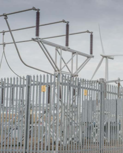
It is proposed to locate the construction compound close to both access options and away from nearby water course crossings. It is also proposed to locate the substation and control building in close proximity to the construction compound.
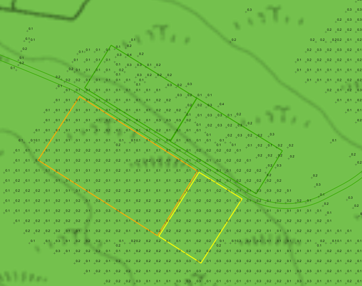
In line with the design principles, the compound would be located on a relatively flat area of land to minimise cut and fill requirements, and therefore disturbance to habitat.
This infrastructure would be located on lower ground to minimise the visual effects of this built infrastructure. The location of this infrastructure also avoids areas of deeper peat.
5.5 Other Considerations
Micrositing
Micrositing of infrastructure (including turbines) of up to 100 m is proposed to minimise environmental effects and allow flexibility in response to Site- specific conditions. The final infrastructure locations will be determined following detailed ground investigation.
Habitat Management Plan (HMP)
An outline HMP has been included to support the application submission. An HMP is an important document associated with requirements for peatland restoration and wider habitat management. In the case of the Proposed Development, the following specific objectives have been identified to support habitat management at the Site.
Peatland Restoration
Black grouse habitat management
Riparian Enhancement and creation
Construction Environment Management Plan (CEMP)
An outline CEMP has been included to support the application submission. A CEMP is an important document associated with the construction works and covers topic areas such as programme of works, hours of operation, roles and responsibilities, site management practices, construction methods, drainage and pollution prevention, reinstatement works, and specialist plans such as species protection plans.
Batching Plant
There is the potential that the Site would operate a batching plant. This temporary batching plant would likely be located in one of the borrow pits once established, (BP1 or BP2), and in close proximity to the main turbine development and set back from water courses.